Converting ER Diagram to Relational Model
The ER model is used for conceptual design, while the relational model is used for logical design. Converting an ER diagram into a set of relational tables is an important process in designing a database. Below are the rules and steps involved in this conversion:
1. Entity to Table Conversion
Strong Entity:
Each strong entity becomes a separate table.
- The table includes all simple attributes of the entity.
- The primary key of the entity becomes the primary key of the table.
Example:
Entity: Student(SID, Name, Age)
→ Table: Student(SID PRIMARY KEY, Name, Age)
Weak Entity:
A weak entity cannot exist without a strong entity and hence:
- Becomes a table with its attributes and a foreign key referencing its owner entity.
- Primary key is usually a combination of the foreign key and its partial key.
Example:
Weak Entity: Dependent(Name, Age) owned by Employee(EID)
→ Table: Dependent(EID, Name, Age)
Primary Key = (EID, Name); EID is a foreign key referencing Employee.
2. Attributes to Columns
Simple Attributes:
Directly become columns in the table.
Composite Attributes:
Only atomic attributes are included, not the composite group.
Example:
If Address = {Street, City, Zip}, include Street, City, Zip as separate columns.
Multivalued Attributes:
Create a new table to handle the multivalued attribute.
- This new table includes the primary key of the original entity and the multivalued attribute.
- A combination of these two forms the primary key.
Example:
Entity: Student(SID, Name, PhoneNumber*)
→ Tables:
Student(SID PRIMARY KEY, Name)StudentPhone(SID, PhoneNumber)with (SID, PhoneNumber) as primary key
Derived Attributes:
These are not stored in the table but can be computed from other attributes when required.
3. Relationship to Table Conversion
1:1 Relationship:
Add the primary key of one entity as a foreign key in the other.
-
Can be placed in either entity’s table, depending on total participation.
Example:Person(PID) and Passport(PassportNo)
→ Add PID as foreign key in Passport or vice versa.
1:N Relationship:
Add the primary key of the “1” side as a foreign key to the “N” side.
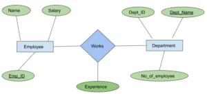
Example:Department(DID) and Employee(EID) with 1:N
→ Add DID as foreign key in Employee
M:N Relationship:
Create a new table for the relationship.
- Include foreign keys from both entities.
- These together form the composite primary key of the new table.
Example:Student(SID) and Course(CID) with M:N
→ Table: Enrollment(SID, CID) where SID and CID are both foreign keys and form the primary key.
Relationship with Attributes:
If a relationship has attributes (e.g., Date, Role), and it’s 1:1 or 1:N, the attributes go to the same table where the foreign key is added.
In case of M:N, the attributes go to the new relationship table.
4. Special Cases in ER Conversion
Specialization/Generalization:
- Create a table for the superclass and subclass.
- Superclass table contains common attributes and primary key.
- Each subclass table includes:
-
-
Primary key (same as superclass)
-
Specific attributes
-
Primary key of subclass is also a foreign key referencing the superclass.
-
Example:
Superclass: Employee(EID, Name)
Subclass: Engineer(SkillSet)
→ Tables:
Employee(EID, Name)Engineer(EID PRIMARY KEY, SkillSet)
(EID is also a foreign key referencing Employee)
Aggregation:
Convert the main relationship as a regular table with all its components.
- Include foreign keys from the entities involved in the aggregation.
- Also include foreign keys from the aggregated relationship if needed.
Summary of Steps
| ER Component | Conversion Rule |
|---|---|
| Strong Entity | Table with all attributes, primary key |
| Weak Entity | Table with foreign key and partial key as primary key |
| Simple Attribute | Column in table |
| Composite Attribute | Break into atomic columns |
| Multivalued Attribute | Separate table with foreign key |
| Derived Attribute | Not stored, computed on demand |
| 1:1 Relationship | Foreign key in one of the entity tables |
| 1:N Relationship | Foreign key in the “many” side |
| M:N Relationship | New table with foreign keys and attributes |
| Specialization | Superclass + subclass tables |
| Aggregation | Convert relationship and aggregate entities as needed |
